ZX Spectrum RS232 information (PLATOTERM)
I will probably re-order this page when I have more material published.
! ! ! WARNING - USB TO SERIAL ADAPTORS ! ! !
If you have every thing setup correctly but you get garbage on your terminal suspect the USB to serial device
HL340 has been found to not work with the spectrum
RS232 +12V -12V is not TTL, avoid TTL devices these are for microcontrollers etc
If a device does not list your OS then it won't have a working driver
Look for PL2303 and WINDOWS 10 Compatible, they usually cost a little more
(Prolific PL-2303 HXD USB to RS-232 Serial Adaptor Compatible with Windows 7 8 10)
! ! ! WARNING - DIVMMC/DIVIDE NMI LOADER ISSUE ! ! !
Don't use the NMI Loader to load PLATOTerm from the TAP file.
You must load the TAP file using the Dot commands.
Loading using the NMI loader will result in bizarre Handshake line handling which produces garbage.
(Credit Ivan and Petr for working this out)
Below are the command to change folder, insert the TAP file as a tape and the old faithful LOAD""
.cd folder
.tapein PLATO.TAP
LOAD ""
WiFi Modems based on Zimodem firmware (bozimmerman) -- not Espressif ESP-AT Modem
Make sure to configure the modem correctly, we need some additional settings.
DTR always High fixes the "no Carrier" issue when connected to a BBS system.
ATb9600
AT&K3
ATS54=2
(Thanks, James!)
Pentium 4 and Core2DUO era Motherboard serial ports
After a long trouble shooting session with Alistair, SUPERIO chips on both his systems
caused an unstable connection that would drop out after a few bytes. My guess is these chips are
cut down RS232 implementations that are not quiet following the expected standards.
If you have a machine from early 2000s, keep in mind the port might be at fault.
(fix in this case was to use a USB Prolific Serial dongle)
IF1 / 128K+ rs232 & tcpser - IRATA.ONLINE PLATO (just enough information)
This is the just enough information version. This is the bare bones to get your spectrum connected to a PC with TCPSER running to dial out. So there will be precise do this instructions, no explanations and the confusing stuff left out. Mainly intended for getting you on PLATO or using other Z88DK based programs. I assume you have a serial port or USB to Serial adaptor on the PC or PI running TCPSER. Downloaded the Platoterm for the setup being used IF1 or PLUS.
Jump to the required section
Then follow on TCPSER Instructions
Jump to the required section
- PLUS to PC Direct (+2/+3)
- Retro Computer Shack cable to PC (converter cable required)
- Interface1 to PC (48K and 128K toast rack)
Then follow on TCPSER Instructions
PLUS to PC Direct
Bill of parts
Wire the plugs below pin to pin as per the chart. DON'T LOOK AT THE PIN NAMES IN THE MANUAL.
Use a marker pen to mark pin 1 on the casing, no seriously do it.
Bill of parts
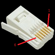
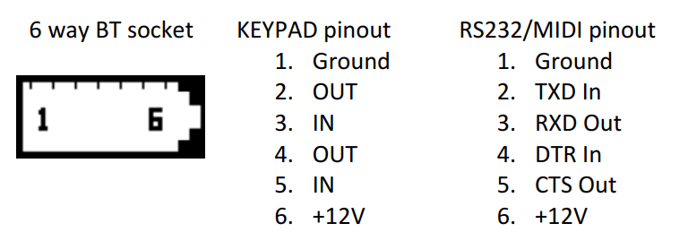
- The ZX Spectrum serial port accepts a 631W plug
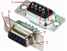
- The PC accepts a 9 pin Female D sub
Wire the plugs below pin to pin as per the chart. DON'T LOOK AT THE PIN NAMES IN THE MANUAL.
Use a marker pen to mark pin 1 on the casing, no seriously do it.
|
|

|
RETRO COMPUTER SHACK CABLE TO PC
Bill of parts
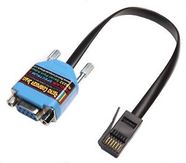
You may have purchased this little gem from retro shack, it needs a cable to convert the handshake to RTS/CTS.
Double check the connections are correct by using a multimeter. Connect the cable and the dongle, test from the BT plug to the PC end against the chart above.
Use a marker pen to mark pin 1 on the casing, no seriously do it.
*untested I don't have one! Let me know if its right!
Bill of parts
- Retro computer shack cable
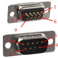
- The Retro computer shack accepts a 9 pin Male D sub
- The PC accepts a 9 pin Female D sub
You may have purchased this little gem from retro shack, it needs a cable to convert the handshake to RTS/CTS.
Double check the connections are correct by using a multimeter. Connect the cable and the dongle, test from the BT plug to the PC end against the chart above.
Use a marker pen to mark pin 1 on the casing, no seriously do it.
*untested I don't have one! Let me know if its right!


INTERFACE 1 TO PC (48K or 128K)
Bill of parts
Use a marker pen to mark pin 1 on the casing, no seriously do it.
Bill of parts
- The IF1 accepts a 9 pin Male D sub
- The PC accepts a 9 pin Female D sub
Use a marker pen to mark pin 1 on the casing, no seriously do it.
|
IF1 side
|
|
PC side
|
TCPSER Instructions
So having assemble the lead and tested it with a meter to ensure pin to pin is correct on your fully assembled cable you are on to the next bit TCPSER. If you haven't tested your cable. Keep your soldering iron warm, you probably didn't mark the pin 1...
Get a copy of TCPSER, there is one in my FILES under PC I have used and it works (windows 10). There are others most of them are source code on GITHUB, but google about and you will find it. If you are running Linux, repositories or compile it from source.
Unpack it to a folder on your system, some where near root is a good idea. The program is run from the command line, these are the basic of the command you will need to know/adjust and issue to start up. Linux users will need to add their user accounts to the group "dialout" or use sudo, or you will get errors launching TCPSER.
TCPSER -s "baud rate" -d /dev/"Com port" -i "&K3"
So,
- -s defines the baud rate, miss match and you get crap on the terminal.
- -d is the device, even windows user need to use /dev/ per the Linux convention.
- -i is the initialisation string the modem is started with in " ". You must use "&K3", if you used "&K0" you get junk if you don't issue it nothing happens. The &K is the Handshake mode which MUST be RTS/CTS for any Z88DK based programs (PLATOTerm)
TCPSER -s 9600 -d /dev/COM1 -i "&K3"
This will start TCPSER up with a baud of 9600, using COM1 with correct Handshaking.
If you want to have the TCPSER start and Dial a connection change "&K3" to "&K3&DTDaddress.com:port". Replacing address.com with the IP or DNS name, the port being the port number of the service being called.
For irata.online PLATO simply load the plato term on your speccy, then run the command
If you want to have the TCPSER start and Dial a connection change "&K3" to "&K3&DTDaddress.com:port". Replacing address.com with the IP or DNS name, the port being the port number of the service being called.
For irata.online PLATO simply load the plato term on your speccy, then run the command
TCPSER -s 9600 -d /dev/COM1 -i "&K3&DTDirata.online:8005
128K Machines RS232 port hardware (Models 128K +2 +2a +3a +3b)
*Work in progress!
This section is worth a read even if you are only interested in writing software. As the hardware is directly driven with software there is a direct relationship which effect the behaviours of both. Reading the +3 manual references to the serial port are usually in the context of using a serial printer. The port is fully capable of sending and receiving data with handshaking. Oddly the handshaking pins are labelled as one pin from each handshaking pair RTS/CTS and DTR/DSR. This may be to make wiring to a serial printer simple.
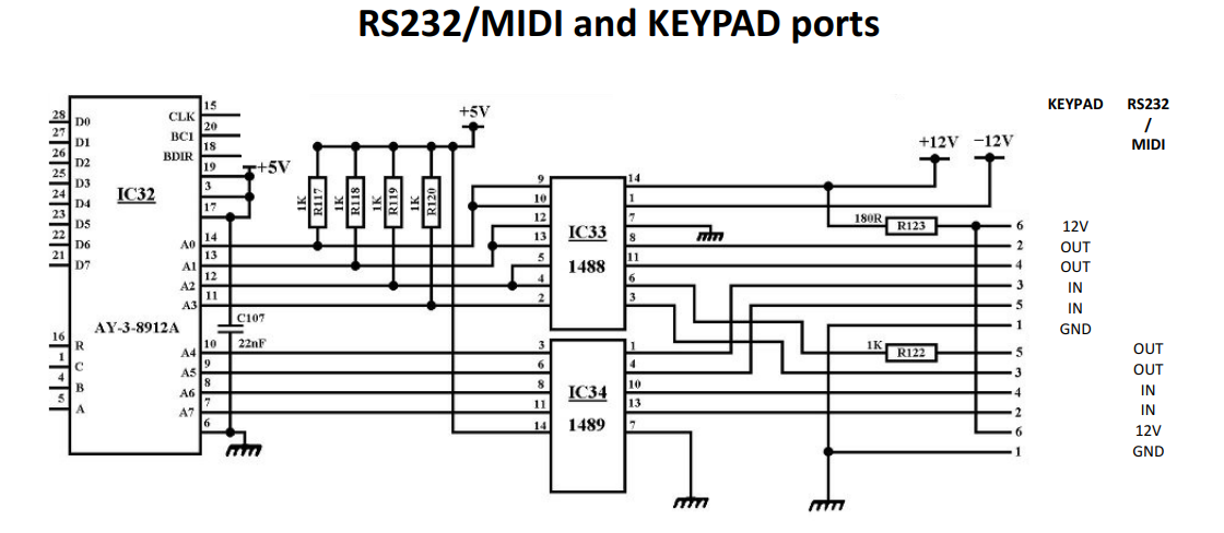
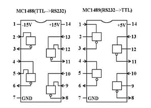
The first important note on the ZX Spectrum's serial port implementation is that it does not use any buffering or RS232 chip sets. The port is software driven VIA the AY-3-8912A chip using IC33(1488) and IC34(1489) chips as line drivers. The AY chip uses 5V TTL where as RS232 swings between +12V -12V (24V peek to peek!), IC33 and IC34 merely shift between the two levels.
The first important note on the ZX Spectrum's serial port implementation is that it does not use any buffering or RS232 chip sets. The port is software driven VIA the AY-3-8912A chip using IC33(1488) and IC34(1489) chips as line drivers. The AY chip uses 5V TTL where as RS232 swings between +12V -12V (24V peek to peek!), IC33 and IC34 merely shift between the two levels.
Images from Ben Versteeg's documentation: https://www.benophetinternet.nl/hobby/vanmezelf/ZX_Spectrum_Midi_Out.pdf
|
Check out Ben's services and shop
|
The manual (corrected) and identify the pin out on the back of the machine.
|
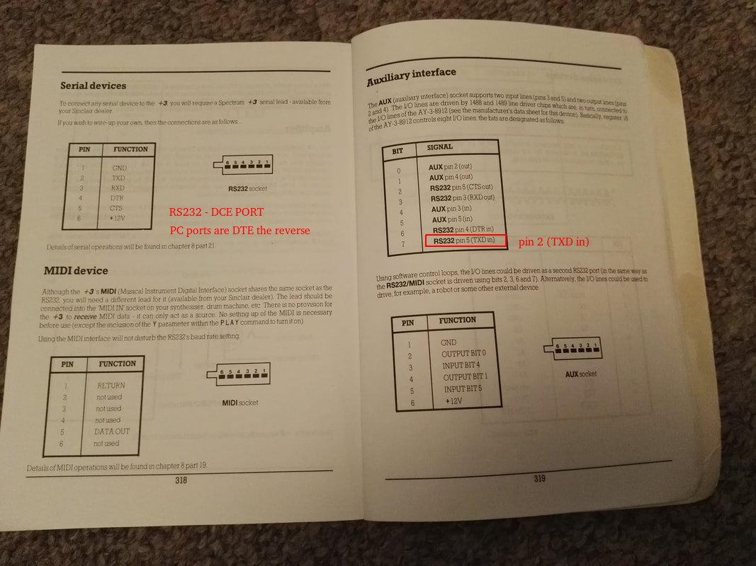
Each pin is an OUTPUT or an INPUT, the signal meaning is determined by software driving the port (especially in the case of handshaking). The next tricky bit is getting around the DCE and DTE labelling schemes. For some reason DCE labelling is used on what these days would be labelled as DTE. Not mentioning this in the manual clearly causes confusion, especially if DTE is assumed.
The DCE/DTE labels, relate to the signal label and the direction. Example, DTE TXD is considered OUTPUT, DCE TXD is considered as an INPUT. If a DTE device is a PC and the DCE device is a Modem. This scheme makes an easy straight through pin to pin connection. TXD to TXD matching labels, reasonably intuitive. Yet deeply counter intuitive when reading the labels meaning. A transmission sent is thus output. Reception is an inbound transmissions, thus received is input. Therefore we need to cross pins TXD and RXD (Outputs connect to Inputs) which is true when connecting DTE to DTE. Should the AUX port pins be used, note the directions change on the PINs. This would lead me to suspect the RS232 port might have been intended as the AUX port. If the ports labels are swapped, the pin outs perfectly matches to DTE. If this was discovered after the case labels had been set in the manufacturing process. The cheapest solution would be to update the software, than to re-tool the manufacturing process. Thus the confusing mess that has been left with a DTE device labelled as DCE. |
Wiring chart
|
128K Machine rs232 - cable designing
* Work in progress
For applications written using the Z88DK driver library you will only need the RTS/CTS cable. The library uses the handshaking lines closely to end byte by byte using CPU time (bit bashing). I haven't tested but DTS/DSR handshaking should work as well if your PC app supports it.
As the serial port is software driven there are many other possible ways to use the port with custom machine code routines. There are also several options when it come to wiring the BT connector to a DB9 connector for more "standard" fittings. The interface1 port also suffers from the being none standard, if you own both a plus machine and an IF1 then you may want an IF1 style tail.
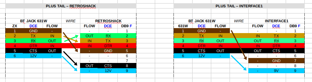
I have created a spreadsheet to help in designing cables. By copying out the predefined tables, aligning them and colouring the signal paths. You can quickly rationalise new cable configurations.
As the serial port is software driven there are many other possible ways to use the port with custom machine code routines. There are also several options when it come to wiring the BT connector to a DB9 connector for more "standard" fittings. The interface1 port also suffers from the being none standard, if you own both a plus machine and an IF1 then you may want an IF1 style tail.
I have created a spreadsheet to help in designing cables. By copying out the predefined tables, aligning them and colouring the signal paths. You can quickly rationalise new cable configurations.
With a +2/+3 machine it is worth making up one tail and then designing the leads required to work off the one tail.
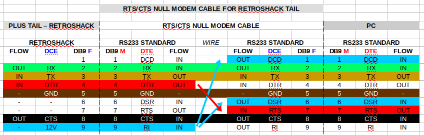
*Retroshack - Retro Computer Shack
*Retroshack - Retro Computer Shack
Using the PLUS TAIL - Retroshack you would then build an RTS/CTS Null modem cable (the middle section) as below
128K machine rs232 - SOFTWARE (DRIVER ROUTINES)
*Work in progress
Section for notes on concepts behind writing software drivers for controlling the port
Software defined ports and signalling
Using signals from the CPU the lines of the AY chip are read or set by the processor to read/generate the RS232 signals. This is why the port can also be used for MIDI. Changing the signals produced by software on the CPU we can produce various patterns. Any electronically compatible system could be driven, assuming the 3.5Mhz CPU is able to respond in time. Modern microcontrollers such as Ardunio use these software based port implementations, they do run at a considerably higher clock speed though!
How fast is the port?
That comes down to a machine code execution rate problem, how long does it take to fetch and execute the commands to read/write the AY chip.
Timing (real time constraints)
For signalling timing is critical (1% accuracy on bit timing). To create perfectly timed signals the running program needs to give way periodically for the driver routines to execute. This is further complicated with the other hardware devices which are implemented using processor interrupts. Keeping track of the time between port interactions can be achieved in may different ways.
Using the Z88DK RS232 library as an example the assembly routines for RS232 turn off the Interrupts. In turning off the interrupts the uncertainty of execution is removed, the CPU can not be interrupt. The CPU will not switch an unpredictable routine of unknown execution time. Dedicating the CPU to one task for a duration of signalling, at the cost of ignoring ALL other system functions enable perfect timing to be achieved. This does give rise to some challenges when using the port. It does however make it possible to calculate timing for driver routines and thus tune to signal timing.
Handshaking can be used to help the processor determine quickly if there is a need to run signalling routines or to return the program. Ready to Send and Clear to Send signals are checked before engaging the longer data transmission routines.
Buffering
Using a buffer with in the ASM driver level might improve on the connection speed. While you can implement and loop calls to the routing in a higher level language. Catching more than one byte at a time, would remove the time over head for the call to fetch a byte. Keeping the buffer short is desirable, remembering the screen refresh rate is 20ms and fetching 1 byte at 9600 baud is roughly 1ms.
|
ASSEMBLY
When programming in assembly the bits on the AY chip are mapped to the pins as follows. |
Programming chart
|
128K MACHINE RS232 - USING Z88DK RS232 (SERIAL) LIBRARY
* Work in progress
Z88DK has a serial library for using the serial port on the 128K machines, RS232PLUS (RS232plus3)
This library implements RTS/CTS handshaking, requiring an appropriate cable. While it is possible to override handshaking with hardware, this will cause problems when reading data. Sending data with handshaking overridden seems to function correctly assuming the other device has an RS232 buffer with space. These devices will always immediately being reception of data independent of the processor.
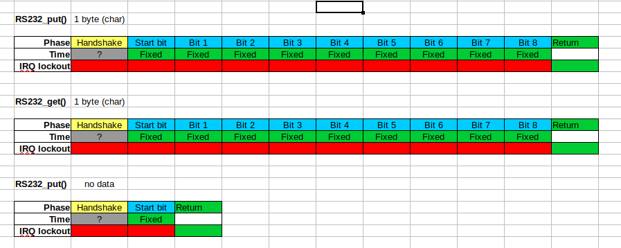
Interrupt requests are disabled when calling the RS232_put() and RS232_get() routines. When the IRQs are disabled, keyboard scanning is halted thus any keys pressed will not be captured. This also includes failing to read any keys held down for longer than the IRQs are off. IRQs must be enabled before any key is pressed to be successfully detected. Therefore the time taken to run the put/get routines needs to be taken in to consideration, as the machine will dedicate to the task. Depending on the selected baud rate, the duration of the lock out will change. Each routine only reads or sends a single character to the remote machine. Multiple calls are required to send streams of data. Spacing these repeat calls with other routines may be important if the program is require to respond to other request.
Interrupt requests are disabled when calling the RS232_put() and RS232_get() routines. When the IRQs are disabled, keyboard scanning is halted thus any keys pressed will not be captured. This also includes failing to read any keys held down for longer than the IRQs are off. IRQs must be enabled before any key is pressed to be successfully detected. Therefore the time taken to run the put/get routines needs to be taken in to consideration, as the machine will dedicate to the task. Depending on the selected baud rate, the duration of the lock out will change. Each routine only reads or sends a single character to the remote machine. Multiple calls are required to send streams of data. Spacing these repeat calls with other routines may be important if the program is require to respond to other request.
|
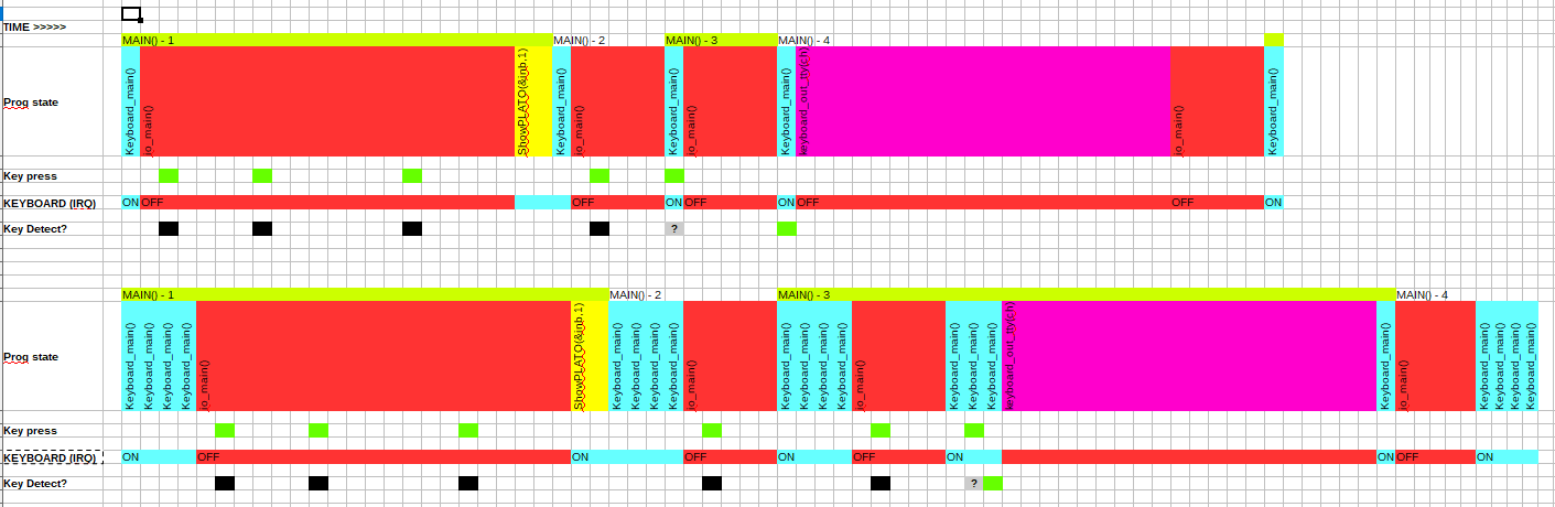
Sending and receiving a single character will lock out IRQs for a fixed period depending on the baud rate. There is an unknown delay that is based on the handshake signals from the remote system. If there is no data to be received the RS232_get() will return sooner than it would if collecting a byte. This behaviour can lead to race conditions, where the no response branch of code becomes too short to be successfully interrupted by a keyboard event. Below shows the Platoterm timing issue |
|
Sample code, reduced from the test API code from Z88DK documentation
C code
Reference material
Links to other sites
Description |
Link |
RS232 guide |
|
Covers voltages and signal timing to generate an RS232 signal |
FUSE IF1 Serial emulation
FUSE Serial notes
Fuse only supports serial on IF1, and IF1 only works on 48K or 128K machines NOT +2 or +3! There are 2 ways to use FUSE serial port emulation for connecting to TCP/IP. You can use a null modem port between two serial ports (on the same host or separate). Alternatively SOCAT can be used to connect a file to a remote system.
NULL Modem method
A null modem cable can be used to join two ports on the same machine, TCPSER and Fuse can then be connected to a port each. Connecting both to the same port does not work! Fuse also does not work with handshaking in the same way as a real spectrum. So we need to disable the RTS/CTS handshakes in TCPSER and FUSE (actually done in the startup command example). Keep this in mind when developing software under emulation, the handshake process is removed. This is probably more critical for anyone writing ASM driver routines.
The following example is using PLATOTerm to connect to IRATA.ONLINE using TCPSER, connecting two USB2Serial devices back to back with a null modem cable.
Linux port configure Baud rate (MUST)
USB Serial device
stty -F /dev/ttyUSB0 ospeed 9600 ispeed 9600 -crtscts
stty -F /dev/ttyUSB1 ospeed 9600 ispeed 9600 -crtscts
(OR)
Running a Putty session configured correctly will configure the serial port for you like below.
stty -F /dev/ttyUSB0 0:0:80000cbd:8a20:3:1c:7f:15:4:0:1:0:11:13:1a:0:12:f:17:16:0:0:0:0:0:0:0:0:0:0:0:0:0:0:0:0
stty -F /dev/ttyUSB1 0:0:80000cbd:8a20:3:1c:7f:15:4:0:1:0:11:13:1a:0:12:f:17:16:0:0:0:0:0:0:0:0:0:0:0:0:0:0:0:0
(OR)
Real serial ports
stty -F /dev/ttyS0 ospeed 9600 ispeed 9600 -crtscts
stty -F /dev/ttyS1 ospeed 9600 ispeed 9600 -crtscts
STTY config string generated by PUTTY session on serial port
Launch Fuse (128 machine using USB1 RX&TX Interface 1 TURN OFF handshake!)
fuse --machine 128 --rs232-rx /dev/ttyUSB1 --rs232-tx /dev/ttyUSB1 --interface1 --no-rs232-handshake $1
(load platoterm from TAP file in fuse)
Now launch TCPSER with the auto-dial routine -- NOTE We turn off handshake with &K0 the opposite to real hardware!)
./tcpser -t sS -s 9600 -d /dev/ttyUSB0 -i "&k0&atdtirata.online:8005"
SOCAT method
Using two terminal windows, one for socat and the other to launch FUSE. Change the tcp: section to the address of the service you want to connect to. In the example below ./V1 is the file to be used as the serial connection, this can be a full path and any name (just be consistent). When using socat to connect to services you won't need to use AT command, socat will open the connection as soon as FUSE is launched. You need to use accelerated loading, select your options and start the terminal quickly before the connection times out.
socat pty,raw,echo=0,link=./V1,wait-slave,b9600 tcp:irata.online:8005
fuse --machine 128 --rs232-rx ./V1 --rs232-tx ./V1 --interface1 --no-rs232-handshake $1 --tape "name of the Tape file"
